The transition from the block diagram of a system differential and algebraic equations is convenient to build a matrix using a mathematical model.
The process for obtaining a matrix of a mathematical model occurs in stages and, for example, for the system shown in Figure 14, is as follows.

Figure 14. Block diagram of the system under study
The first action must be to conduct a sequential sequentially numbered units according to the type of link: dynamic links, reinforcing links summarizing units and non-linear element.
Thus, in the scheme originally numbered 2 dynamic link, and then amplifying unit 2, 2 summarizes the management and non-linear element 1 (see. Figure 15).
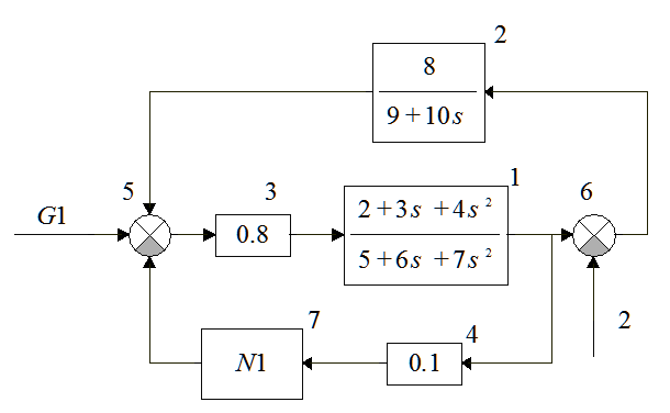
Figure 15. Block diagram with numbered links
Following the numbering units of the output signal for convenience it is defined as Y with an index number of the link (see. Figure 16).
Figure 16. Block diagram with numbered units and output signals
For each element of the system is the description that contains a set of input actions, state variables and output actions. State variables are specified only for dynamic links and comprise two indices - number of the link in the diagram and the number of the state variable in the transfer function. The number of state variables is the order of the denominator polynomial of the transfer function.
Thus, the description of the elements will be obtained:
1 - (Y3, {x11, x12}, Y1);
2 - (Y6, {x21}, Y2);
3 - (Y5, Y3);
4 - (Y1, Y4);
5 - ({+Y2, -Y7, +G1}, Y5);
6 - ({+Y1, -2}, Y6);
7 - (Y4, Y7);
The amount of differential equations is 3 (the number of state variables), and the number of algebraic equations is equal to 7 (number of units). Then matrix mathematical model will have 3+ lines 7 and 3 + 7 + 1 columns.
In general, the matrix mathematical model consists of six sub-block matrix, with 3 sub-matrix in the upper part of the matrix are reserved for differential equations, and 3 sub-matrix in the lower part - for algebraic equations (see. Figure 17).

Figure 17. Appearance matrix mathematical model
Filling in the matrix of the mathematical model is carried out by successive consideration of each link in the system, depending on its type. Each link has only one line at the bottom of the matrix corresponding to the level number, and if the link is dynamic, that is the top of the line corresponding to the variables the state of this link.
1. Dynamic units are filled at the top and bottom of the matrix.
a). In the upper middle portion at the intersection with lines of state variables is allocated a column corresponding to the output level. In the lower middle part at the intersection with a line-level stands cell numbers in the same column. The cells marked with the sign reversed downward denominator coefficients are written, starting with the free term.
b). In the upper middle portion at the intersection with lines of state variables is allocated a column corresponding to the input level. In the lower middle part at the intersection with a line-level stands cell numbers in the same column. The cells marked with his sign is written from top to bottom of the numerator polynomial coefficients, starting with the free term. If a link directly operates the external action, the inlet column is the last one (t), which must be on the same rule to record the coefficients, but their further multiplied by the amount of external impact.
at). In the upper left portion at the intersection of rows and columns of the state variables recorded submatrix in which diagonally arranged below the main unit, and the rest zeros.
g). At the bottom left at the intersection of row number and column level with the state variables recorded submatrix, wherein in the rightmost cell is a unit and the rest zeros.
2. Reinforcement units are filled in the lower part of the matrix.
a). In the lower middle part at the intersection with a line-level rooms allocated cell in the column corresponding to the output level, which is written "-1".
b). In the lower middle part at the intersection with a line-level rooms allocated cell in the column corresponding to the input level recorded gain. If a link directly operates the external action, the inlet column is the last one (t), which is necessary to record the gain multiplied by the amount of external impact.
3. Summation units are filled in the lower part of the matrix.
a). In the lower middle part at the intersection with a line-level rooms allocated cell in the column corresponding to the output level, which is written "-1".
b). In the lower middle part at the intersection with a line-level rooms are allocated cells in the columns corresponding to the input-level impacts, which is written "1" if the sign on the adder is positive, "-1" if the negative sign on the adder. If a link directly acting external influence, in column 1 (t) is written sign adder multiplied by the amount of external impact.
4. The nonlinear units are filled in the lower part of the matrix.
a). In the lower middle part at the intersection with a line-level rooms allocated cell in the column corresponding to the output level, which is written "-1".
b). In the lower middle part at the intersection with a line-level rooms allocated cell in the column corresponding to the input level recorded by the conversion from the entrance level, divided by the input level. If a direct link is valid external action, the input column is the last 1 (t), to be recorded in the conversion function of the external influence.
Schematically, the process of filling the matrix mathematical model of the system under study is shown in Figure 18.
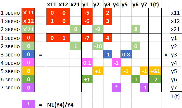
Figure 18. Filling in the matrix of the mathematical model
At the top of the matrix of the mathematical model by multiplying matrices written system of differential equations (9).
| | 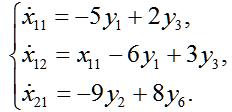 | (9) |
At the top of the matrix of the mathematical model by multiplying matrices written system of algebraic equations (10).
| |  | (10) |
Example of mathematical models
Principles of mathematical models of systems are best considered at particular abstract examples, for which part of the system information may be omitted.
Example 1: Dynamic link and the external effect shown in Figure 19.

Figure 19. Block diagram of the system for example 1
Then matrix mathematical model of the system under study takes the form (11):
| | 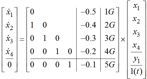 | (11)
|
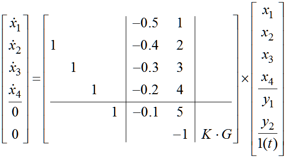
Example 2. Dynamic unit and the amplifying unit with an external impact are shown in Figure 20.

Figure 20. Block diagram of the system for Example 2
Then matrix mathematical model of the system under study takes the form (12):
| |  | (12)
|
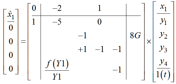
Example 3. A system for all types of elements shown in Figure 21.

Figure 21. Block diagram of an example 3
Then matrix mathematical model of the system under study takes the form (13):
| |  | (13)
|