Under the synthesis system is meant finding the parameters entered into the system controller, which allows to reach the required performance specification, including the constraints of time and the transient oscillation index.
The idea of synthesis of linear control systems in a time domain root method is that for the structural scheme of the system shown for example in Figure 1 is the characteristic polynomial, and the known system requirements calculated desired characteristic polynomial, then the coefficients of the polynomials are equal and for obtaining the equations equates to determined parameters regulators.

Figure 1. Block diagram of the controlled system
Given the structures of the corrective bonds and unknown parameters is carried out in them the description of the whole system in the form of differential equations describing the behavior of the free system (1):
| |  | (1) |
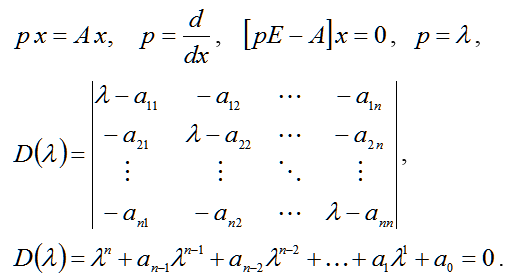
Then the characteristic equation (1) takes the form (2):
| |  | (2) |
In expression (2) are functions of the coefficients of a synthesized parameter. The desired characteristic equation for the system is given by (3):
| |  | (3) |
All λi roots of the characteristic equation (3) are considered to be known and defined by the user or automatically calculated by the program. Consequently, the coefficients bi equations are also known, as calculated by the known equation roots. The equations (2) and (3) is in the form of equations (4):
| |  | (4) |
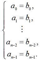
Equating the resulting equations will be determined by the values of the unknown parameters of the required system (5):
| |  | (5) |
Thus, all the unknown coefficients correcting links can be obtained by solving the system of equations (5). Thereafter, the obtained values are substituted into the system, and it is performed simulation. If the simulation results are satisfactory, the synthesis is successful. Otherwise, changes may be made within the required characteristics of a system consisting of, for example, to increase the time of transition.
Selection controller.
The basic rule when choosing the order of the transfer function of the controller is about the equality of the whole system and the number of unknown parameters introduced regulators. In addition, input controller must be as small as possible in order. The transfer functions of regulators for 0, 1, and 2 orders of magnitude are shown below (6):
| |  | (6)
|
Thus, if the same part of the system is necessary, and the order of 3 to enter one controller, its transfer function can only be W22 (p), as then the order of the system is equal to 3 + 2 and the number of unknown parameters (B0, B1, B2, A0, A1) is also equal to 5.
When you select the desired characteristic equation roots of the following applies. In order for the system to become stable during the transition process which is approximately equal to tpp vibration μ, you must choose the dominant root in the left half (7):
| |  | (7) |
The value of μ is chosen on the basis of technical requirements. In the absence of more information, the value of the index is taken equal to 1.6. The initial value of the real part α0 calculated as follows (8):
| |  | (8) |
All of the following values of the real part of the increase in 1.5-3.0 times the previous value and the value of the imaginary part is recalculated according to the value of the real part.
An example of the synthesis of a simple object.
Figure 2 shows a block diagram of an object consistent with a correction device, required to ensure the establishment of processes for 1 second. The order of the system without introducing corrector is 1 ,. Since the selected simple corrector, the order of which does not increase the order of the system and the number of unknown parameters is equal to the total order system with a corrector, thus correcting device for the system will be equal to W0 (p) = K.
Figure 2. Block diagram of the object
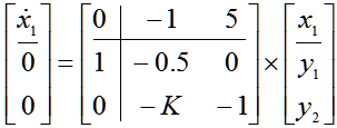
On the block diagram is compiled matrix mathematical model of a system that has the form (9):
| |  | (9) |
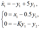
By matrix mathematical model of the system are recorded differential and algebraic equations (10):
| |  | (10) |
Expressing outputs units and putting them in a differential equation is the differential equation and the matrix A (11):
| |  | (11) |
After that, the program is administered SintACS synthesis matrix A (see. Figure 3), is given by the transition process and the algorithm for the calculation.
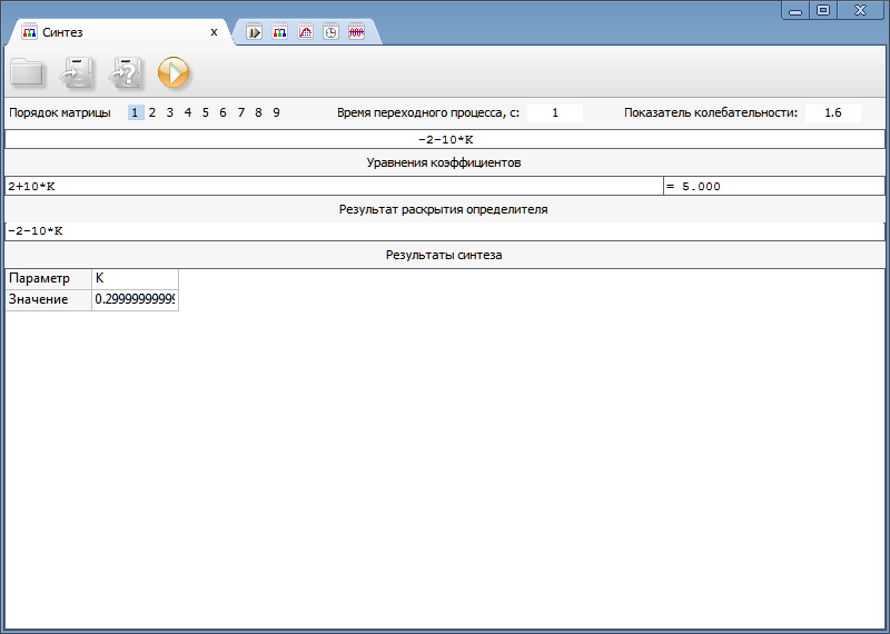
Figure 3. Dialog SintACS
As a result of the synthesis is received value of parameter K, which is equal to 0.3.
An example of the synthesis of a complex object.
A system with three unknowns regulators shown in Figure 4 is required to determine the structure of controllers and their parameters are found to transients completed in 0.9 seconds.
Figure 4 Block diagram of the system in general
Then, selected according to the rules regulators are shown in the block diagram in Figure 5.
Figure 5. Block diagram of the selected units
By eliminating from further consideration external action and an adder to which it operates, it will be obtained generalized structure of the system. The resulting system has a fifth order, and the number of parameters is synthesized 5. Since the order of the system and the number of unknown parameters are equal, it is possible to use the synthesis of corrective devices.
The matrix mathematical model of the system under study has the form (12):
| | 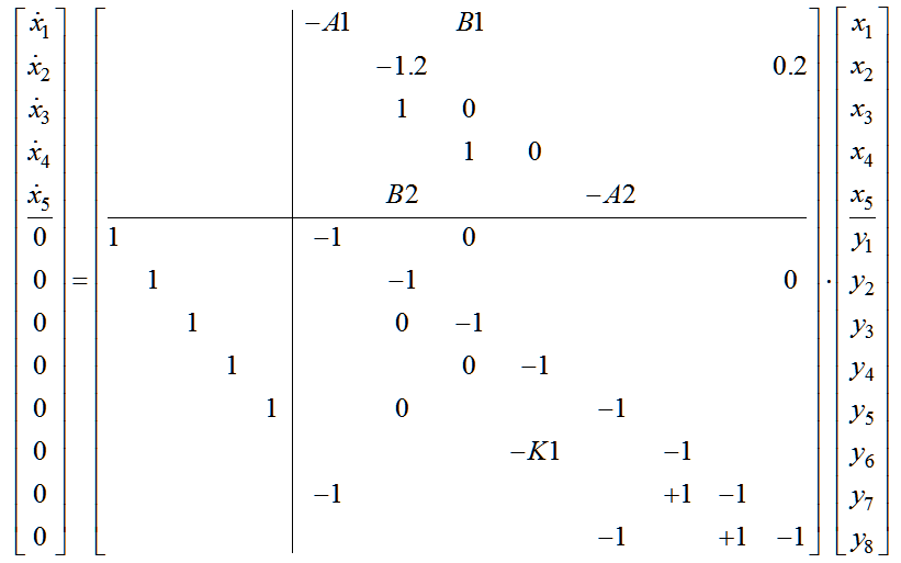 | (12) |
According to the mathematical model is a matrix differential equation (13):
| | 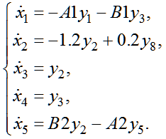 | (13) |
According to the mathematical model is a matrix algebraic equation (14):
| | 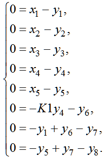 | (14) |
After that, in (14) are expressed in all of the signals y (15):
| | 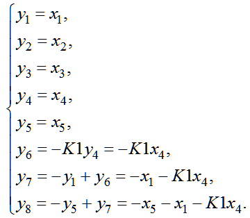 | (15) |
Then the system of differential equations (13) takes the form (16):
| | 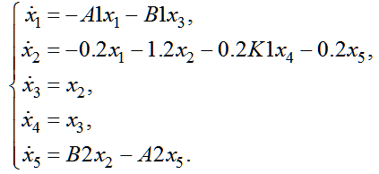 | (16) |
The resulting system of differential equations (16) is represented in the matrix form (17):
| | 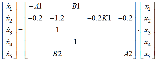 | (17) |
On the basis of the matrix (17) is produced in a synthesis program SintACS, dialog box shown in figure 6.
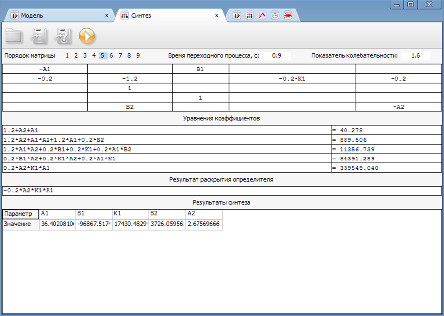
Figure 6. The dialog box for the complex system SintACS
Substituting these values in units of regulators, will be obtained a block diagram of a system that is shown in Figure 7.
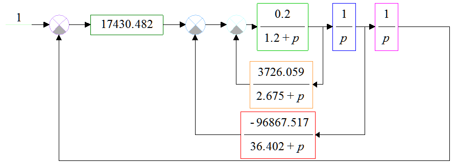
Figure 7. Model of the studied system in SimACS
The modeling system will be received graph of the output of the system (see. Figure 8).
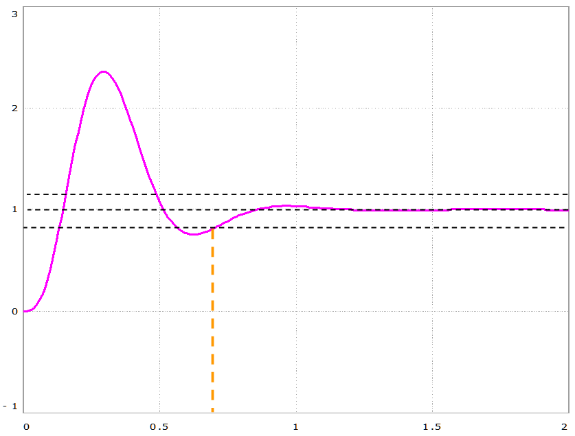
Figure 8. Graph of the transition process
As follows from the above chart, the transient time is 0.7 seconds and not more than specified in the terms of reference of time 0.9 seconds. Therefore, the synthesis of the system was conducted successfully.
Obtaining characteristic equation in symbolic form.
To study the system shown in Figure 9, to obtain the characteristic equation in symbolic form with the help of the program SintACS as follows.

Figure 9. Block diagram of the system under study
Then the differential equations in matrix form for the study will take the form of (18):
| |  | (18) |
The program is written SintACS the matrix A, calculations are performed in the lines will get the desired characteristic polynomial coefficients, which are presented in Figure 10.
Figure 10. Dialog SintACS in finding the coefficients of the characteristic polynomial
Thus, the program is received SintACS 2 ratio characteristic polynomial: zT2+zT1 and zT1*zT2+zT1*K1*zT2*K2. Then, performing back substitution for zT1 and zT2, characteristic polynomial is obtained in symbolic form (19):
| |  | (19) |
Moreover, the characteristic polynomial may be obtained by a classical method, by equating the denominator of the transfer function of the closed system K1K2 + 1 / (1 + pT1) (1 + pT2) to zero. After transformations calculated decision will be equal to the solution (19) obtained in the program SintACS.
Preparation of transfer functions for the block diagram.
To study the system shown in Figure 11, to obtain the transfer function of the closed system of error in symbolic form using the program SintACS as follows.

Figure 11. Block diagram of the object
The transfer function of error (Y3 / U) program SintACS can be calculated by calculating the two matrices. For their preparation, to be recorded without a mathematical model of the system state variables in the submatrix of algebraic equations. For the dynamic elements of the main diagonal of the denominators for the outputs are written in reverse, and at the entrances - the numerators with its sign. For summing and amplifying units are recorded on the main diagonal -1 (20):
| |  | (20) |
Then, by the condition of the problem is necessary to determine the transfer function of the following form (21):
| | 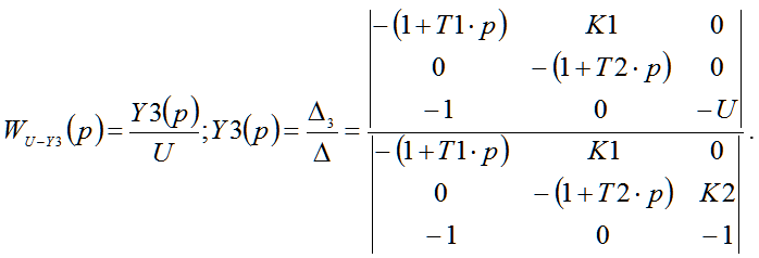 | (21) |
Upper determinant obtained by replacing the third column of the fourth, but with the opposite sign. It reflects the transfer function of the adder Y3 when applying effects U. Lower determinant corresponds to a closed system. Consistently determinants in deciding SintACS, will get the transfer function of the closed system error in symbolic form (22):
| |  | (22) |
In addition, the transfer function of the closed system can be obtained by the classical method and is equal to 1 / (1 + K1K2 / (1 + pT1) (1 + pT2)). After transformations calculated decision will be equal to the solution (22) obtained in the program SintACS.